


Description
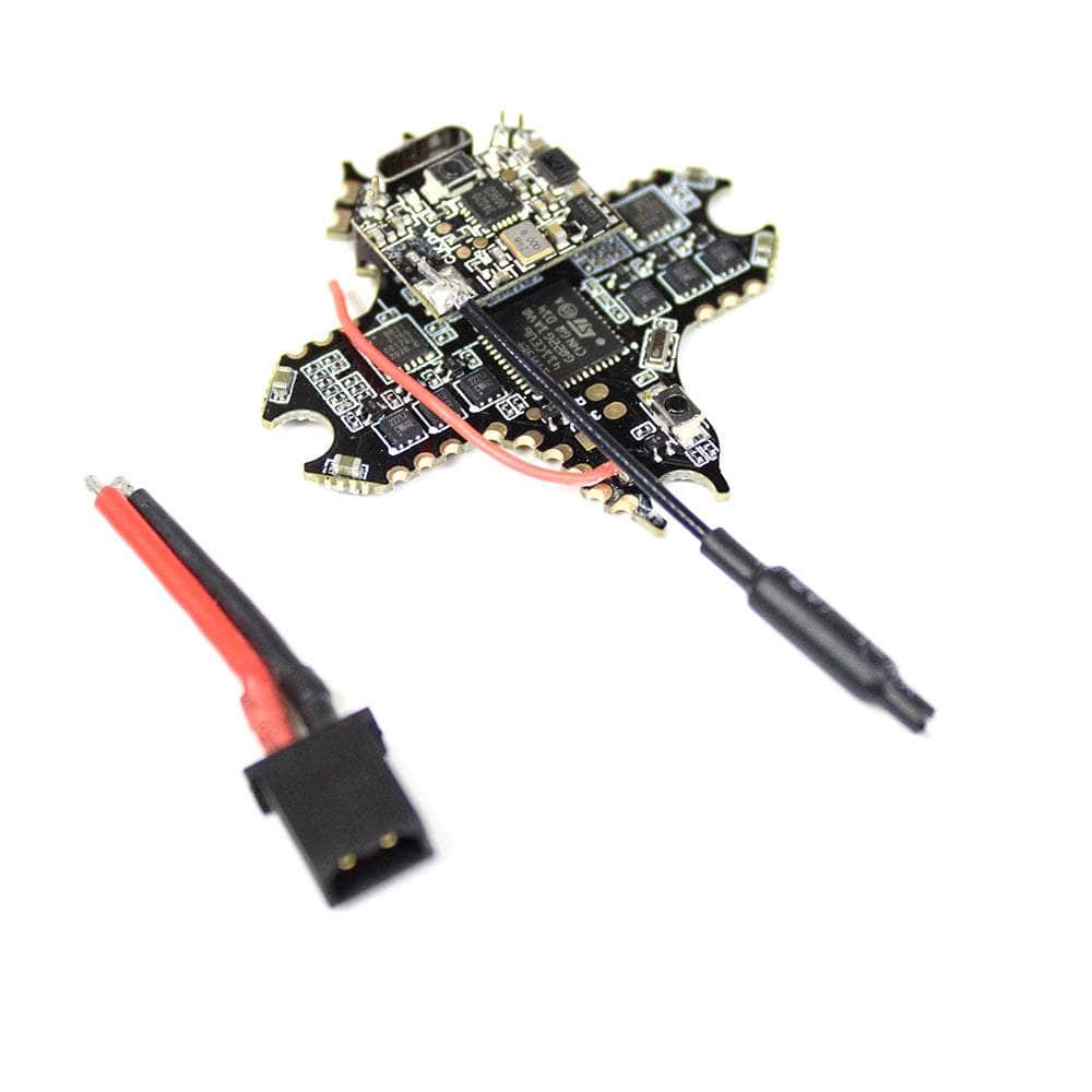
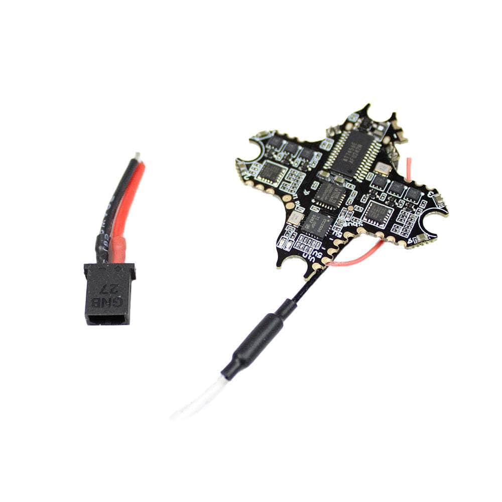
The SpeedyBee F4 3-6S 20×20 Stack/Combo (F405 FC / 35A 8bit 4in1 ESC)! Experience feature-rich performance and an unbeatable price for a 20×20 stack. Utilizing an upgraded F405 flight controller chip with better performance than the F411. it features a built-in Bluetooth chip for seamless wireless Betaflight tuning. The board comes with a 4-level battery voltage display. built-in barometer. and supports connectivity to all DJI Air Units. It offers 4 available UART ports. and a dual BEC setup with 5V 2A and 9V 3A outputs. This ESC provides four synchronized outputs with a continuous current of 35A. delivering strong power to drive all 2-4 inch and lightweight 5-inch quadcopters via 4-6S battery. Equipped with a TVS transient suppression diode onboard. it better absorbs surge voltage. providing enhanced protection for the ESC.
Features
- User Manual
- DJI compatible
- Feature-rich
- Budget-friendly price point
- Compatible with M2 and M3


Specifications
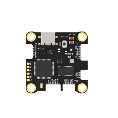
- Product Name: SpeedyBee F405 Mini BLS 35A 20×20 Stack
- Flight Controller: SpeedyBee F405 Min
- ESC: SpeedyBee BLS 35A Mini V2 4-in-1 ESC
- Bluetooth: Supported. Used to connect with the SpeedyBee App for flight
- controller and ESC parameter configuration. Please make sure the MSP switch on
- UART 4 is turned on and set to a baud rate of 115200. otherwise Bluetooth
- functionality will not be available.
- WiFi: NOT Supported
- Wireless FC Firmware Flashing: NOT Supported
- Wireless: Blackbox Download & Analysis NOT Supported
- Power Input: 3-6S LiPo
- Mounting: 20 x 20mm 3.5mm hole size . Compatible with M2 and M3
- screws/Silicone grommets
- Dimension: 32mm(L) x 35mm(W) x 14.2mm(H)
- Weight: 13.5g
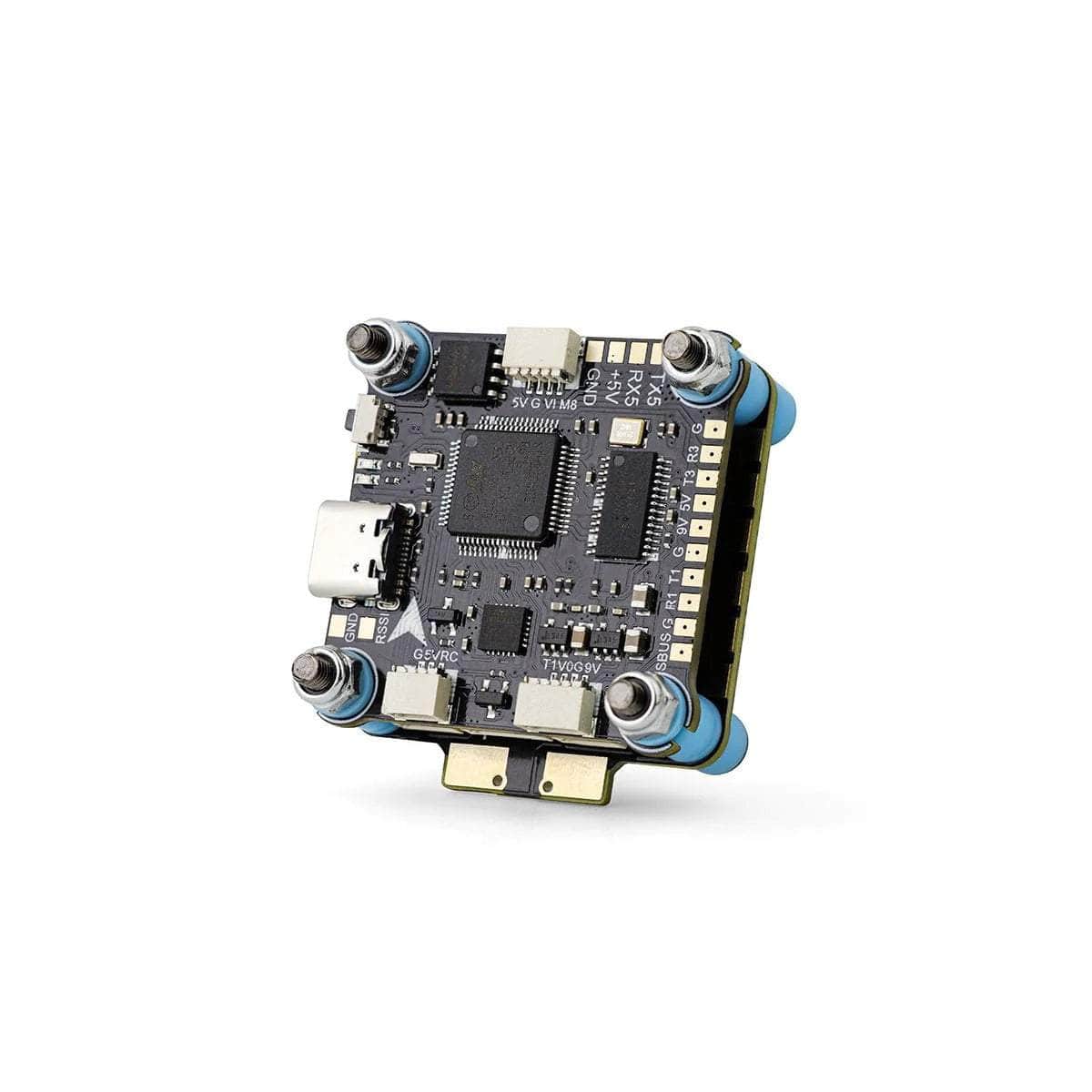
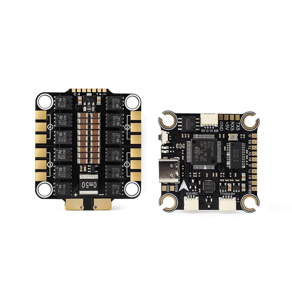
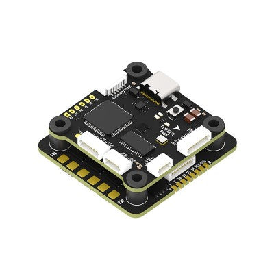
SpeedyBee F405 V3 30×30 Flight Controller
- MCU: STM32F405
- IMU(Gyro): ICM42688P
USB Port Type: Type-C - Barometer: Built-in
- OSD Chip: AT7456E chip
- BLE Bluetooth: Supported. Used to connect with the SpeedyBee App for flightcontroller and ESC parameter configuration. Please make sure the MSP switch on UART 4 is turned on and set to a baud rate of 115200. otherwise Bluetoothfunctionality will not be available.
- Wireless FC Firmware Flashing: NOT Supported. Please connect to the Betaflightconfigurator on the PC to do FC firmeare update
- Wireless Blackbox Download & Analysis: NOT Supported. Please connect to theBetaflight configurator on the PC to do blackbox analysis.
- WIFI: Not supported
- DJI Air Unit Connection Way: Direct soldering
- DJI Air Unit Compatibility: Compatible with all DJI Air Units: DJI O3/RunCamLink/Caddx Vista/DJI Air Unit V1. Please use the solder pads < 9V. G. T1. R1. G. SUBS(R2) > on the front right corner of the flight controller to make a pin-to-pin connection with the solder pads on the DJI Air Unit. UART1(T1. R1) is used for OSD and SUBS(R2) is used for DJI Air Unit’s internal SBUS receiver signal input.
- Blackbox: 8MB Onboard Flash
- BetaFlight Camera Control Pad: Yes(CC pad on the front side)
- Current Sensor Input: Supported. For SpeedyBee BLS 35A V2 ESC. please setScale=250 and Offset=-500.
- Power Input: 3-6S LiPo. The flight controller is powered through the G. V wires ofthe 8pin harness or G. V pads from the bottom side of the flight controller.
- 5V Output: 4 groups of 5V output. three +5V pads and 1 BZ+ pad( used for
- Buzzer) on front side. The total current load is 2A.
- 9V Output: 1 group of 9V output. one +9V pad on front side. The total currentload is 3A.
- 3.3V Output: Supported. Soldering pad named ‘3V3’ on the front top of the flightcontroller. Designed for 3.3V input receivers. Up to 500mA current load.
- 4.5V Output: Supported. Designed for radio receiver and GPS module even whenthe FC is powered through the USB port. Up to 1A current load.
- ESC Signal: M1 – M4 wires or soldering pads on bottom side.
- UART: 6 sets(UART1. UART2. UART3. UART4(Dedicated for Bluetooth connection)).UART5(Dedicated for ESC telemetry).UART6
- ESC Telemetry: UART R5(UART5)
- I2C: Supported. DA & CL pads on front side. Used for magnetometer. sonar. etc
- Traditional Betaflight LED Pad: Supported. 5V. G and LED pads on bottom of thefront side. Used for WS2812 LEDs controlled by the Betaflight firmware.
- Buzzer: BZ+ and BZ- pad used for 5V Buzzer
- BOOT Button: Supported. Press and hold BOOT button and power the FC on at the
- same time will force the FC to enter DFU mode. this is for firmware flashing whenthe FC gets bricked.
- RSSI Input: Not Supported
- Smart Port / F.Port: Not Supported
- Supported Flight Controller Firmware BetaFlight(Default). INAV
- Firmware Target Name: SPEEDYBEEF405MINI
- Mounting: 20 x 20mm 3.5mm hole diameter. Compatible with M2 and M3
- screws/Silicone grommets.
- Dimension: 30(L) x 32(W) x 7.8(H)mm
- Weight 9.6g
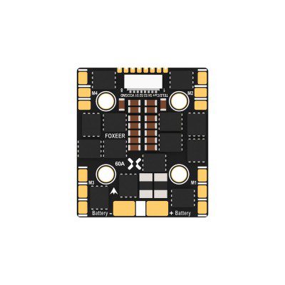
SpeedyBee 35A BLHeli_S Mini V2 4-in-1 ESC
- Firmware: BLHeli_S J-H-40
- Continuous Current: 35A x 4
- Burst Current: 45A(5seconds)
- ESC Protocol: DSHOT300/600
- Power Input: 3-6S LiPo
- Power Output: VBAT(Battery voltage. used to power the flight controller)
- Current Sensor: Support (Scale=250 Offset=-500)
- Mounting: 20 x 20mm 3.5mm hole size. compatible with M2 and M3 screws/Silicone grommets.
- Dimension: 35 x 35 x 5.5mm
- Weight: 7.2g
Includes
- 1x SpeedyBee F4 3-6S 20×20 Stack/Combo (F405 FC / 35A 8bit 4in1 ESC)
Wiring Diagram

There are no reviews yet.